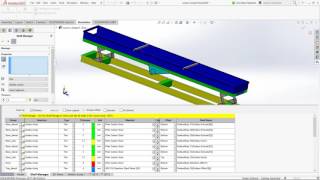
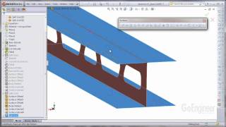
Media Summary: This video highlights the process of using the You can display the mesh and results of shells using a 3D representation of Learn about "CAD Conditioning" process you can use to modify frame components to accept

Solidworks Simulation 2013 Shell Thickness - Detailed Analysis & Overview

This video highlights the process of using the You can display the mesh and results of shells using a 3D representation of Learn about "CAD Conditioning" process you can use to modify frame components to accept To begin, download a FREE 30-Day trial of the Power Surfacing RE add-in for

Photo Gallery

SolidWorks Simulation 2013 - Shell Thickness Display
SolidWorks Simulation - Using the Shell Thickness as a Variable in a Design Study
New in SolidWorks Simulation 2013: Render Shell Thickness in 3D
SOLIDWORKS Simulation Shell Definition
Why SolidWorks Simulation - Easy handling of large models that need to represented by Shell elements
SIMULATION TUTORIAL: 3 ways to create Shell Elements in SOLIDWORKS Simulation
SOLIDWORKS Simulation Step-Up Series: Shell Strategies Part 2
SOLIDWORKS Simulation Step-Up Series: Shell Strategies Part 1
SOLIDWORKS Simulation - Shell Elements for Frames Tutorial
When SOLIDWORKS Thickness fail | Power Shell Prevails
SolidWorks Simulation: Offset Definition of Shell Elements
SOLIDWORKS โ€“ Using the Multi-Thickness Shell Setting
View Detailed Profile
SolidWorks Simulation 2013 - Shell Thickness Display

SolidWorks Simulation 2013 - Shell Thickness Display

Learn how the new

SolidWorks Simulation - Using the Shell Thickness as a Variable in a Design Study

SolidWorks Simulation - Using the Shell Thickness as a Variable in a Design Study

This video highlights the process of using the

New in SolidWorks Simulation 2013: Render Shell Thickness in 3D

New in SolidWorks Simulation 2013: Render Shell Thickness in 3D

You can display the mesh and results of shells using a 3D representation of

SOLIDWORKS Simulation Shell Definition

SOLIDWORKS Simulation Shell Definition

Learn various methods for defining

Why SolidWorks Simulation - Easy handling of large models that need to represented by Shell elements

Why SolidWorks Simulation - Easy handling of large models that need to represented by Shell elements

One can create and manage

SIMULATION TUTORIAL: 3 ways to create Shell Elements in SOLIDWORKS Simulation

SIMULATION TUTORIAL: 3 ways to create Shell Elements in SOLIDWORKS Simulation

Shell

SOLIDWORKS Simulation Step-Up Series: Shell Strategies Part 2

SOLIDWORKS Simulation Step-Up Series: Shell Strategies Part 2

Learning to use

SOLIDWORKS Simulation Step-Up Series: Shell Strategies Part 1

SOLIDWORKS Simulation Step-Up Series: Shell Strategies Part 1

Learning to use

SOLIDWORKS Simulation - Shell Elements for Frames Tutorial

SOLIDWORKS Simulation - Shell Elements for Frames Tutorial

Learn about "CAD Conditioning" process you can use to modify frame components to accept

When SOLIDWORKS Thickness fail | Power Shell Prevails

When SOLIDWORKS Thickness fail | Power Shell Prevails

To begin, download a FREE 30-Day trial of the Power Surfacing RE add-in for

SolidWorks Simulation: Offset Definition of Shell Elements

SolidWorks Simulation: Offset Definition of Shell Elements

The offset direction of a

SOLIDWORKS โ€“ Using the Multi-Thickness Shell Setting

SOLIDWORKS โ€“ Using the Multi-Thickness Shell Setting

Learn how to use the multi-

SOLIDWORKS Simulation - Shell Manager

SOLIDWORKS Simulation - Shell Manager

SOLIDWORKS