Media Summary: In this detailed example the I²C protocol is used to demonstrate the different views, menus and features of Part one of four. This four-part video introduces our Find out how easy it is to display multiple scope, spectrum and X-Y views in
Picoscope 6 Serial Decoding Basics - Detailed Analysis & Overview
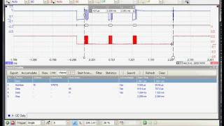
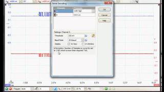
In this detailed example the I²C protocol is used to demonstrate the different views, menus and features of Part one of four. This four-part video introduces our Find out how easy it is to display multiple scope, spectrum and X-Y views in In this part 1 of 2 series I will be covering lab scope scales, time base and trigger settings 00:00 - intro to pico Jon Parker of Pico Technology gives you a brief This videos demonstrates how to use the total power measurement on an RF pulse in spectrum mode. We include high end ...
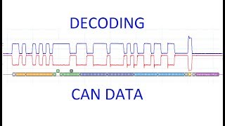
In this video the differential CAN bus signals are acquired and decoded using the Part two of four. This four-part video introduces our This video provides a brief demonstration of how to add and remove automated measurements in spectrum mode (frequency ...