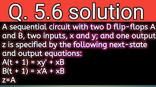
Media Summary: ... our truth table and from there we are going to make a circuit a Q. 5.8: Derive the state table and the state diagram of the LAB 5 BASIC LOGIC GATES AND CIRCUIT ANALYSIS
Lab 5 Sequential Circuit Analysis - Detailed Analysis & Overview
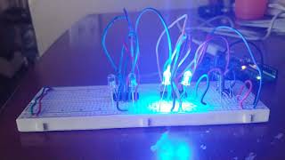
... our truth table and from there we are going to make a circuit a Q. 5.8: Derive the state table and the state diagram of the LAB 5 BASIC LOGIC GATES AND CIRCUIT ANALYSIS Shows the results of my 4 bit binary counter up Timer. Frequency divider. Pulse counting. Pulse Width Modulation. IR remote control. This video demonstrates the functionality of a