Media Summary: Lab 5 Binary Adder and Subtractor Circuit 2020-CS-447 Lab 5: Design and Analysis of Binary Adder and Subtractor Circuits CE 433: Lab 5 Task 1 - Adder/Subtractor with LED binary outputs
Lab 5 Binary Adder And - Detailed Analysis & Overview
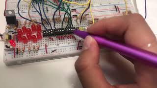
Lab 5 Binary Adder and Subtractor Circuit 2020-CS-447 Lab 5: Design and Analysis of Binary Adder and Subtractor Circuits CE 433: Lab 5 Task 1 - Adder/Subtractor with LED binary outputs I attempt to explain how binary numbers (0's and 1's) are added by the ALU, a component of the CPU using the I would like to design a circuit for adding numbers in