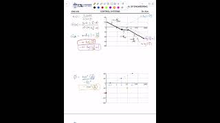
Media Summary: engineering Draw the Bode magnitude plot for the system. engineering Draw the Bode Phase plot for the system. Chapter 10-3 - I/O Equation to Transfer Function

Chapter 10 Transfer Function And - Detailed Analysis & Overview

engineering Draw the Bode magnitude plot for the system. engineering Draw the Bode Phase plot for the system. Chapter 10-3 - I/O Equation to Transfer Function Chapter 10-4 - Transfer Fcn to I/O Equation A quick and easy inspection method is presented to directly write a discrete-time system's Z transform frequency domain methods are used for discrete-time LTI systems described by linear difference equations. MethodsĀ ...

In this video I have solved a circuit containing inductor and capacitor using Laplace transform applications.

Photo Gallery

Chapter 10 Transfer Function and Z-Plane Analysis of LTI Systems
Control Systems - Chapter 10 Frequency Response Techniques
Chapter 10-3 - I/O Equation to Transfer Function
Control Systems - Chapter 10 Frequency Response Techniques
Chapter 10-4 - Transfer Fcn to I/O Equation
Chapter 10 Finding the transfer function H(z) from the Linear Difference Equation
Introduction to Transfer Function
What are Transfer Functions? | Control Systems in Practice
Chapter 10 Z Transform methods for LTI Systems described by Linear Difference Equations
Proof of Block Diagram Transfer Function: G(s)/[1+G(s)H(s)]
View Detailed Profile
Chapter 10 Transfer Function and Z-Plane Analysis of LTI Systems

Chapter 10 Transfer Function and Z-Plane Analysis of LTI Systems

The

Control Systems - Chapter 10 Frequency Response Techniques

Control Systems - Chapter 10 Frequency Response Techniques

engineering #ControlSystems #Bode #BodePlot #MagnitudePlot Draw the Bode magnitude plot for the system.

Control Systems - Chapter 10 Frequency Response Techniques

Control Systems - Chapter 10 Frequency Response Techniques

engineering #ControlSystems #Bode #BodePlot #MagnitudePlot Draw the Bode magnitude plot for the system.

Control Systems - Chapter 10 Frequency Response Techniques

Control Systems - Chapter 10 Frequency Response Techniques

engineering #ControlSystems #Bode #BodePlot #PhasePlot Draw the Bode Phase plot for the system.

Chapter 10-3 - I/O Equation to Transfer Function

Chapter 10-3 - I/O Equation to Transfer Function

Chapter 10-3 - I/O Equation to Transfer Function

Control Systems - Chapter 10 Frequency Response Techniques

Control Systems - Chapter 10 Frequency Response Techniques

engineering #ControlSystems #Bode #BodePlot #PhasePlot Draw the Bode Phase plot for the system.

Chapter 10-4 - Transfer Fcn to I/O Equation

Chapter 10-4 - Transfer Fcn to I/O Equation

Chapter 10-4 - Transfer Fcn to I/O Equation

Chapter 10 Finding the transfer function H(z) from the Linear Difference Equation

Chapter 10 Finding the transfer function H(z) from the Linear Difference Equation

A quick and easy inspection method is presented to directly write a discrete-time system's

Introduction to Transfer Function

Introduction to Transfer Function

Control Systems:

What are Transfer Functions? | Control Systems in Practice

What are Transfer Functions? | Control Systems in Practice

This video introduces

Chapter 10 Z Transform methods for LTI Systems described by Linear Difference Equations

Chapter 10 Z Transform methods for LTI Systems described by Linear Difference Equations

Z transform frequency domain methods are used for discrete-time LTI systems described by linear difference equations. MethodsĀ ...

Proof of Block Diagram Transfer Function: G(s)/[1+G(s)H(s)]

Proof of Block Diagram Transfer Function: G(s)/[1+G(s)H(s)]

Proving the well-touted

Finding the transfer function of a circuit

Finding the transfer function of a circuit

In this video I have solved a circuit containing inductor and capacitor using Laplace transform applications.