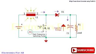
Media Summary: Well I thought I would do a few more experiments with switch-mode power supply type circuits. This time I thought I would try to ... in this video i demonstrated how to design # HOW TO BUILD Boost Converter High Power High Efficiency using
Cdc Electronic Workshop Tl494 Push - Detailed Analysis & Overview
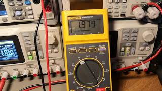
Well I thought I would do a few more experiments with switch-mode power supply type circuits. This time I thought I would try to ... in this video i demonstrated how to design # HOW TO BUILD Boost Converter High Power High Efficiency using I decided to test out a Frequency Modulated singing arc circuit I found, in the past I have experimented with Pulse Width ... Lab-5 Generation of PWM Signal Using IC TL494 (Push Pull mode) Power Electronics Lab Testing this part of the circuits for normal duty cycle and frequency controllers operation. Using a 12v 7Ah battery as the input ...
TL494CN Pulse Width Modulation Control Circuit 17YC8H TL494CN. my first try with subs :-) please comment if it worked for you, or not, (and you dont understand Danish of course)