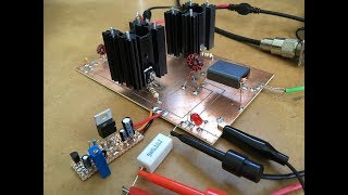
Media Summary: Video looking at what impact varying the output transfomer turns ratio has on the gain of the Video looking at what impact increasing Vcc from 13.8VDC to 24VDC has on the gain of the Schematic available at See Part 6 at Part 2 can be seen at ...
Bd139 Push Pull Amplifier Experiments - Detailed Analysis & Overview
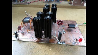
Video looking at what impact varying the output transfomer turns ratio has on the gain of the Video looking at what impact increasing Vcc from 13.8VDC to 24VDC has on the gain of the Schematic available at See Part 6 at Part 2 can be seen at ... Schematic available at See Part 6 at Part 1 can be seen at ... Schematic available at See Part 6 at Part 2 at ... Schematic available at See Part 6 at Replaced the 16V wall adapter ...
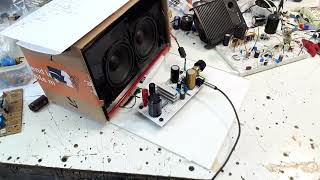
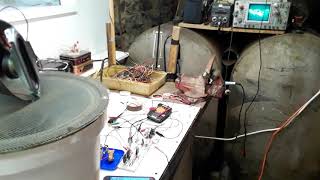
Schematic available at See Part 6 at Replaced the 20V wall adapter ... See updated schematic at Active devices used are LM358 dual op YES... The ceiling is shaking! Schematic available at